
Definition of Alternating Current (AC)
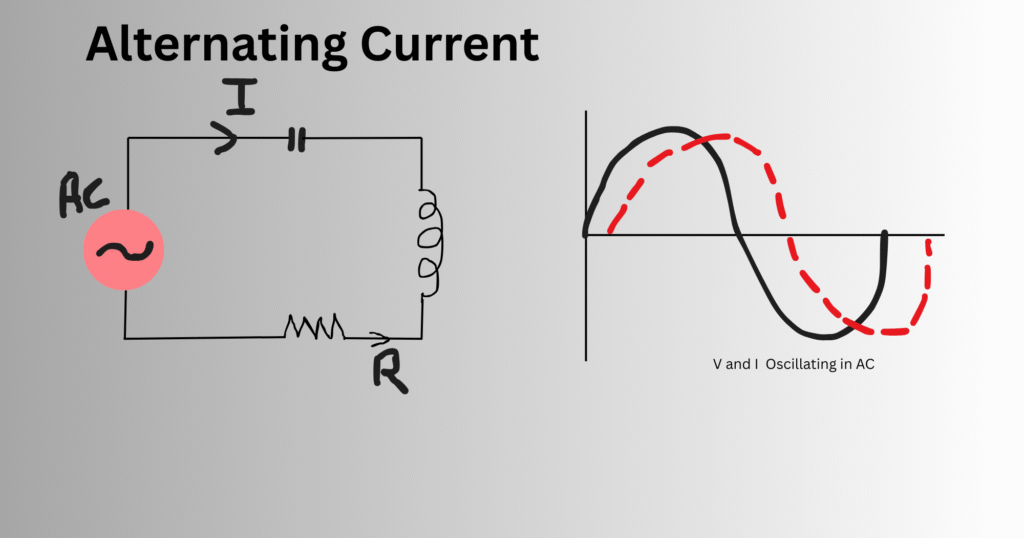
We know in DC circuits, the current is made to flow in a uniform direction. However, electric charge can also flow periodically in reverse direction. This flow of current is known as Alternating Current; The polarity of AC keeps changing at regular intervals. In addition, the voltage and current show an oscillating behavior in a back and forth motion in an AC circuit.
The AC circuit has the ability to transmit power over long range with minimum loss of energy with just one plug of a cable. Transformers are used for the transmission of power from higher to lower voltages as required.
As the current and voltage transform periodically, a waveform is generated which may not always be the same. Frequency is the most common term to describe the waveform. It indicates the number of repetitions of a complete full cycle of that waveform in one second. To make it clear, if the frequency of a power supply is given as 60 Hz, then we can say that the direction of current reverses 60 times per second.
In present days, AC has become a foundation of modern electrical power systems. It can travel electrical power to long ranges, from power plants to homes and factories with high efficiency. Without AC, the large electrical connections and industrial developments were impossible.
Common AC Waveforms: Sine, Square, and Triangle
The waveform of an AC signal can take various shapes which are described as follows:
Sine Wave:
This type of waveform is obtained frequently. It resembles the graph of sine function and the variation with time in voltage and current is sinusoidal. Thus, the energy loss is minimum and an ideal power transmission is obtained. Currently, all power systems apply sine waves.
Square Wave:
In opposition to steady power transmission, the square wave shows a random and sudden fluctuation of voltage and current between positive and negative levels. It cannot be used in long range power transmission. However, it can be utilized for signal processing and some common digital electronics. They can be effectively used in switching and clock signals in a circuit.
Triangle Wave:
In this waveform, the rise and fall in the current and voltage is linear, giving a triangular shape for transmission. Among the three shapes, triangle waves are rarely employed in general. Still, they are widely used in audio synthesizers, testing circuits, and modulation processes.
Each waveform differs according to their harmonic features. Sine waves are only the pure waveforms and other two have higher harmonic compositions and can disturb the efficiency of those systems generating square or triangular waves.
Frequency, Period, and Angular Frequency (Hz and rad/s)
Some terms used generally to describe AC signals are: frequency, time period, and angular frequency.
- Frequency (f): Here, the frequency refers to the number of cycles completed by the waveform of AC signal per second. It is measured in Hertz (Hz). For example, if an AC signal has a frequency of 20 Hz, we have to understand that the waveform repeats 20 times per second.
- Period (T): The time period taken by the signal to complete one full cycle has been termed as period. It is always the reciprocal of frequency:
T=1/f
So, if the given frequency is 20 Hz, then the period is calculated as 1/f = 1/20 = 0.05 seconds.
- Angular Frequency (ω): Angular frequency comes into action when the waveform rotates making an angle of radians per second. It can be represented in terms of normal frequency as :
ω=2πf
These terms and their relationships with each other are the most significant parts while studying AC signals. Power transmission with higher frequencies is faster. But faster the power transmission, the chances of energy loss is greater. The standard frequency for power transmission worldwide is given as 50 Hz or 60 Hz.
Peak, RMS, and Average Values in AC Signals
As AC signals are periodic and time varying, the peak values, average values, maximum and minimum conditions must be studied carefully.
- Peak Value (Vp): This is the maximum value of voltage or current in one half-cycle.
- Root Mean Square (RMS) Value (Vrms): It is the comparison of AC value equivalent to the DC value, when both are serving the same power. For a sine wave:
Vrms=Vp/√2 - Average Value (Vavg): The mean value of the waveform over one half-cycle is the average value. For a sinusoidal wave:
Vavg=2Vp/π
Electrical appliances consume power and it can be related with the RMS values. Therefore, RMS values have special importance in electricity.
Phase Angle and Phasor Basics
In AC systems, voltage and current may or may not be the same with time and their direction and magnitude may also vary. This variation is usually given by the phase angle. Similarly, a phasor gives a graphical representation of these variations between voltage and current.
- Phase Angle (φ): It is the angular difference between the two AC quantities: voltage and current waveforms. If both voltage and current reach their maximum values without any angular difference or a phase angle 0°, they are said to be in phase. On the contrary, if one waveform reaches its peak earlier or later than the other, they are out of phase. For general RLC circuits (resistor, inductor, and capacitor combined), the phase angle is determined by:
θ = tan−1{(XL−XC)/R)} [Equation 1]
Where:
θ = phase angle
XL = inductive reactance
XC = capacitive reactance
R = resistance
- Phasors: A phasor represents the waveforms graphically. The magnitude (or length) of the phasor gives the RMS or peak value of the AC quantity. For example, a sinusoidal current can be represented as:
A(t)=Amsin(ωt+ϕ) [Equation 2]
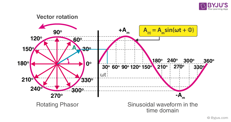
Figure: Phasor diagram for AC
The phasor makes comparison of current and voltage waveforms to a wave and hence makes the AC calculations like additions, substractions, etc. easier and quicker.
Impedance in AC Circuits: Resistance, Inductive, and Capacitive Reactance
As mentioned above, the phase between current and voltage varies and this happens frequently when other electronic devices like capacitors, inductors etc. are used in the AC circuits. These devices can also block the flow of current in certain amounts. This blockage is known as Impedance in the circuits. It is denoted by Z and has the same unit as that of resistance i.e. ohm. However, it is slightly different from the resistance of DC in the way that it also considers the phase difference. It consists a real part called resistance (R) and an imaginary part called reactance (jX) and is combinedly written as;
Z = R + jX [Equation 3]
- Resistance (R): It is the blockage in current due to the resistance present in the circuit and is independent of the frequency of the waveforms. If current and voltage have zero phase angle then, Z = X. The imaginary part vanishes.
- Inductive Reactance (XL): It is the current blockade due to the presence of inductors which depends on frequency of waveforms.
XL = ωL = 2πfL [Equation 4]
where L is the inductance. - Capacitive Reactance (X_C): It is the current opposition due to the presence of capacitors in the circuit and is given by,
XC = 1/ωC = 1/2πfC [Equation 5]
where C is capacitance.
Now the combined total impedance will be,
Z = R+j(XL−XC) [Equation 6]
∣Z∣ =√ R^2+(XL−XC)^2
Impedance determines the flow of current in the circuits.
- Case I: If XL>XC, the circuit is inductive.
- Case II: If XC>XL, the circuit is capacitive
- Case III: If XL=XC, the circuit is at resonance
Resonance in RLC Circuits and Bandwidth
As described above, an RLC circuit contains resistors, inductors, and capacitors. When the inductive reactance is equal to the capacitive reactance (XL=XC), resonance takes place. At this point, their ability to oppose the current cancel each other out. The condition for resonance is given by above case III:
Or, fr = 1/2π√LC [Equation 7]
In a series RLC circuit, the Z is minimum and hence the current blockage is minimum. Hence, the current becomes maximum here (Z=R). On the other hand, in a parallel RLC circuit, Impedance is maximum and results in a minimum current. The resonance is widely employed in the tuning circuits, radios, and filters.
A measure of quality factor is essential to apply resonance in the required circuits. Q-factor measures whether the peak of resonance is flat or sharp.
Q = 1/ω0CR [Equation 8]
Various applications like radio tuners, filters, and oscillators work on narrow bandwidth and hence require high Q-factor, while some applications requiring wide frequency use low measure of the Q-factor.
Bandwidth gives the efficient frequency for the circuit operation. It is defined as the difference between the upper and lower frequencies where the power is exactly half of its maximum value. Mathematically,
BW = f2−f1 [Equation 9]
where f1 and f2 are the lower and upper cutoff frequencies.
A sharper resonance corresponds to a smaller bandwidth, useful in selective frequency applications. Bandwidth and the quality factor are related as:
BW = f0/Q
AC Power Basics: Real, Reactive, Apparent, and Complex Power
In AC circuits, power is more complex than in DC systems.
- Real Power (P): The actual power consumed by the circuit for the purpose of doing useful work is known as real power. Mathematically,
P=VrmsIrmscosϕ; where ϕ is the phase angle. - Reactive Power (Q): It does not perform real work that pops out due to the oscillations of reactive elements. However, it is required to keep balance between the magnetic and electric fields in the inductors and capacitors. It is measured in VAR (volt-ampere reactive).
Q=VrmsIrmssinϕ - Apparent Power (S): It combines both real and reactive power and gives the total power. It is measured in VA (volt-amperes). In other words, it is the product of RMS voltage and current.
S=VrmsIrmsS - Complex Power (S): The power can be represented as a complex power in AC, to show the relationship between real and reactive power. It is given as:
S=P+jQ
Power Factor and Power Factor Correction Methods
Power Factor (PF): It is a measurement done to see how effectively an electric power is converted into useful work.
Power Factor = cosθ = Real Power (P)/Apparent Power (S)
A high power factor indicates that the electric power is efficiently utilized while, while a low power factor means the energy is wasted to overcome the same load and hence the energy is lost in the transmission process.
When the load is inductive, a lagging power factor arises and the current lags behind voltage. Similarly, if the load is capacitive, a reverse condition arises. When the phase between current and voltage is 0, the power factor becomes unity, which is regarded as the most efficient transmission of power and hence no energy is lost. Thus, we can conclude that with the minimum phase difference minimum loss in energy can be obtained.
Methods of Power Factor Correction:
- Capacitor Banks: It is the mostly utilized and affordable method of correction. Capacitors are used to supply leading reactive power (QC) that offsets lagging reactive power of inductive loads. Motors and transformer stations generally use this correction.
- Synchronous Condensers: Here the overexcited synchronous motors used in the circuit act as adjustable capacitors and generative reactive power dynamically. They are used in power plants and grids.
- Phase Advancers: They are specially designed for induction motors as they supply suitable magnetizing current directly and improve the power factor.
- Automatic Power Factor Correction (APFC) Panels: These designations are highly advanced and switch the capacitor banks on or off as per the requirement of load in the circuit.
Three-Phase AC Systems: Line vs Phase Quantities
Three-phase AC systems are much preferred in power generation, transmission, and industrial applications as compared to single-phase systems. They provide a smoother and balanced way to deliver electrical power.
A three-phase system consists of three conductors carrying alternating currents of the same frequency and amplitude but 120° out of phase with each other. The two three-phase system connections are: Star (Y) (connected to a common neutral point) and Delta (Δ) configurations(each ends connected to a closed loop).
Since three AC conductors are connected, a three-phase AC system has three sinusoidal voltages.
We measure voltage and current in two ways: phase quantities and line quantities.
- Line Quantities: Voltages (Phase voltages) or currents (Phase currents) are measured between any two lines of the system.(e.g., R-Y, Y-B, B-R).
- Phase Quantities: Voltages or currents are measured between a line and the neutral point.
In a balanced three-phase star connection:
Vline = √3Vphase
And
Iline = √3Iphase
Three-phase systems reduce the conditions for power loss and gives higher efficiency in transmission.
Transformers: Stepping AC Voltage Up and Down
A transformer is an important device in electricity and magnetism. It functions on the basis of Faraday’s law of electromagnetic induction. It consists of two coils, both wounded around an iron core, carrying magnetic flux:
- Primary winding is connected to the input voltage or the source.
- Secondary winding is connected to the output or load.
There are two types of transformers:
- Step-Up Transformer: The no. of turns in the secondary coil are greater than the primary coil (Ns>Np). The output voltage is greater than the input one. It is best for long-distance transmission that reduces current and power loss.
- Step-Down Transformer: The no. of turns in the primary coil are greater than in the secondary coils. The output voltage becomes lesser than the input. It is generally used in common circumstances like in households and industries which becomes safer for the usage.
As current is changing, the transformers only work with AC. They are highly efficient because they have no other movable parts and hence no internal energy loss is beared. They can make long-distance power transmission efficient at a reduced cost. Thus, they have become a most important device for the distribution and transmission of electrical energy.
Generation, Transmission, and Distribution of AC Power
The AC circuit is fulfilled by three main steps which are as follows:
- Generation: AC is generated in power plants using alternators driven by turbines (steam, hydro, or wind).
- Transmission: Electricity is transmitted at high voltages to reduce losses.
- Distribution: Step-down transformers are used to reduce voltage and distribute it at the local level.
This system makes sure that the power is reached up to the consumers reliably and efficiently.
Converting Between AC and DC: Rectifiers and Inverters
- Rectifiers: They are the electronic circuits to convert AC to DC. They are employed in certain electronic devices like chargers and power supplies. The DC produced after rectification is a pulsating DC. Therefore, capacitors and inductors are used to make the DC steady. Different available rectifiers are the half-wave, full-wave, and bridge rectifiers.
- Inverters: It is a device that converts DC to AC. They are mostly used in solar power systems, UPS devices, and renewable energy integration.
These devices fulfill the gap lying between AC and DC applications.
Harmonics and Total Harmonic Distortion (THD) in AC Systems
In AC systems, dynamic loads—like computers, LEDs, and variable frequency drives—create harmonics. The waveform can be affected by harmonics, which are multiples of the fundamental frequency.
fn = n 🇽 f1; [fn = harmonic frequency, f1 = fundamental frequency, n = harmonic order]
Harmonics can have several negative impacts like heating of the device, voltage distortion, overload in the conductors, errors in meter readings, resonance etc.
Total Harmonic Distortion (THD): It is the measure of how much disturbance the harmonics offer in the device.
THD = √V2^2+V3^2+V4^2+⋯/V1 [Equation 10]
Using filters like passive filters, active filters, K-rated transformers, phase-shifting transformers, etc. can mitigate the problems of harmonics in the devices.
Measuring AC: Multimeters, Clamp Meters, and Oscilloscopes
Accurate measurements are needed for safe and efficient use of AC in the circuits. For the measurement, following tools or devices can be used:
- Multimeters: Can measure RMS voltage, current, and resistance.
- Clamp Meters: Using clam meters allow clamping around the conductor and measure the current without interrupting the circuit.
- Oscilloscopes: It can display the waveform types, frequency, and phase relationships in real time.
Safety Considerations and Standards for Working with AC
Working with AC is hazardous as it includes electric shocks, burns, and fire hazards. Safety precautions must be applied which includes;
- Using insulated tools and protective gear.
- Following lockout-tagout (LOTO) procedures.
- Keeping circuits properly grounded.
- Following safety standards such as IEC, IEEE, and NEC for safe installations.
Conclusion
AC is the source that lights up our house in the dark nights and makes us charge our gadgets reachable in our bed. The simple local level power transmissions to complex power plants energy-distributions are done by the AC. All AC features are studied under concepts such as impedance, resonance, power factor, and harmonics.
The broad application of transformers, three-phase systems, and advanced power electronics demonstrates how adaptable and open AC is. At the same time, dependable and secure actions are provided by measuring instruments and strict safety rules.
Today huge corporations with domestic appliances cannot operate without AC. It is a milestone in the history of science and technology that has been recognized even by a zero-physics knowledge.
References
Bartiromo, R., & De Vincenzi, M. (2016). Alternating Current: Basic Circuits for Applications. In Electrical Measurements in the Laboratory Practice (pp. 127-161). Cham: Springer International Publishing.
Rajput, R. K. (2002). Alternating current machines. Firewall Media.
Barreto, G., & Murari, C. A. F. (2014). Basic Concepts for Alternating Current through Educational Videos. Journal of mechanics engineering and automation.
Hooge, C. (2016). 20.5 Alternating Current versus Direct Current. BCIT Physics 0312 Textbook.
https://en.wikipedia.org/wiki/Alternating_current
https://byjus.com/jee/alternating-current