
The electric current along a conductor is eligible to produce a magnetic field around it. This effect is known as the magnetic effects of electric current. This is a naturally occurring fundamental phenomena which is the principle of electromagnetism. Thus, electricity and magnetism are two indispensable quantities. An electric charge at rest has only an electric field, but when it starts its journey along a conductor, it is surrounded with a magnetic field as well. The phenomenon was first observed by Hans Oersted in 1820 and hence made the first discovery of electromagnetism.
Like an electric field, a magnetic field also has its magnitude and direction. However, the properties solely depend upon the strength of the current, shape of the conductor and the distance from the conductor. Various laws like Biot- Savart law, Ampere’s circuital law, etc., also describe the relation between the current and the magnetic field.
Electromagnetism has contemporarily become an inseparable part of our daily life. The power generators and set ups like electric motors, generators, transformers and electromagnets are the major examples of today’s applications. Understanding the magnetic effects of electricity will elaborate the concept of power generations and make our equipment and technologies more advanced and efficient.
Oersted’s Experiment: Discovery of Current-Produced Magnetic Fields
Before 1819, electricity and magnetism were considered as two unique quantities and no connection was studied between them. The Danish physicist Hans Oersted accidentally showed this demonstration while performing a lecture for some students. He noticed a deflection on the compass needle when current was passed through the nearby wire. This observation left a huge impact on him and continued further investigation.
Oersted placed a compass above a wire connected to a battery. When the power was supplied, current started flowing on the wire which moved the needle of the compass. He also carried out his investigation by reversing the direction of the current. This made the deflection of the compass just in the opposite direction of the current. Finally, he was able to detect the inter-relationship between the current and the magnetic field. Later, in July 1820, he reported his findings in the meeting of the French Academy of Science.
A number of scientists were inspired by this big report and started their own investigations. Among them, Jean-Baptiste Biot and Felix Savart worked combinedly and André Marie Ampère carried out unique studies and did remarkable work by investigating the forces exerted on magnets by currents. Similarly, François Arago discovered that iron could be magnetized by a current. Humphry Davy, also studied the force of magnet on the conducting wire. Within 10 years of Oersted’s discovery, Michael Faraday found that the motion of a magnet can also produce current on a conducting wire. This finding showed that both electric and magnetic fields are equally capable of generating each other and create a huge impact on each of them.
Magnetic Field Lines and Conventions Around Conductors
Magnetic field lines are the imaginary straight lines found around a current-carrying conductor. They denote the strength and direction of a magnetic field. Their greater density means the greater magnetic effect and vice-versa. Their direction is north to south, outside the magnet and south to north inside a magnet. Hence, in a complete visualization, they complete a loop while moving outside and inside the magnet. Also, remember that, the density of field lines keeps on decreasing on moving apart from the magnet.
The magnetic field lines form concentric circles around a straight wire whose direction is provided by the current’s flow. Thus the field line patterns help us to visualize how electricity generates magnetism. Different shapes of wires like straight wires, loops, solenoids, and other conductors can give different patterns of the magnetic field lines. The direction of current flow affects the direction of these field lines, which is easier to find out using the right-hand thumb rule:
Right-Hand Thumb Rule for Field Direction
The Right-Hand Thumb Rule is a method used to identify the specific direction of the magnetic field and the current that produces it, inside a conductor. It helps practically to visualize the relationship between electric current and thus produced magnetic field.
According to this rule, if we hold a straight conductor in the right hand, then the thumb gives the direction of the electric current (from positive to negative terminal) and the curl of the fingers around the conductor gives the direction of the magnetic field lines around it.
The direction of current can be seen in two ways: if the current is flowing upward through a vertical wire, the thumb points upward, and the fingers curl around the wire in an anticlockwise direction. Conversely, if the current flows downward, the magnetic field goes clockwise. It can be concluded from here that the direction of the magnetic field is always opposite to that of the current..
This rule was implemented as the first practical visualization of Oersted’s discovery. It is widely used in physics and electrical engineering to know the direction of magnetic fields around straight wires, solenoids, and loops.
Biot-Savart Law: Magnetic Field Due to Current Elements
The Biot-Savart Law deals with the quantitative and qualitative nature of magnetic fields produced by a steady electric current. It establishes a mathematical relationship between the electric current (I) of any section of the wire and the magnetic field (B) that the section induces. Hence, it shows the dependence of the magnetic field with the amplitude, path, length, and location of the current. The Biot-Savart law fully satisfies Ampere’s circuital law and Gauss’ theorem. Like Coulomb’s law in electrostatics, Biot-Savart law is extremely important in magnetostatics.
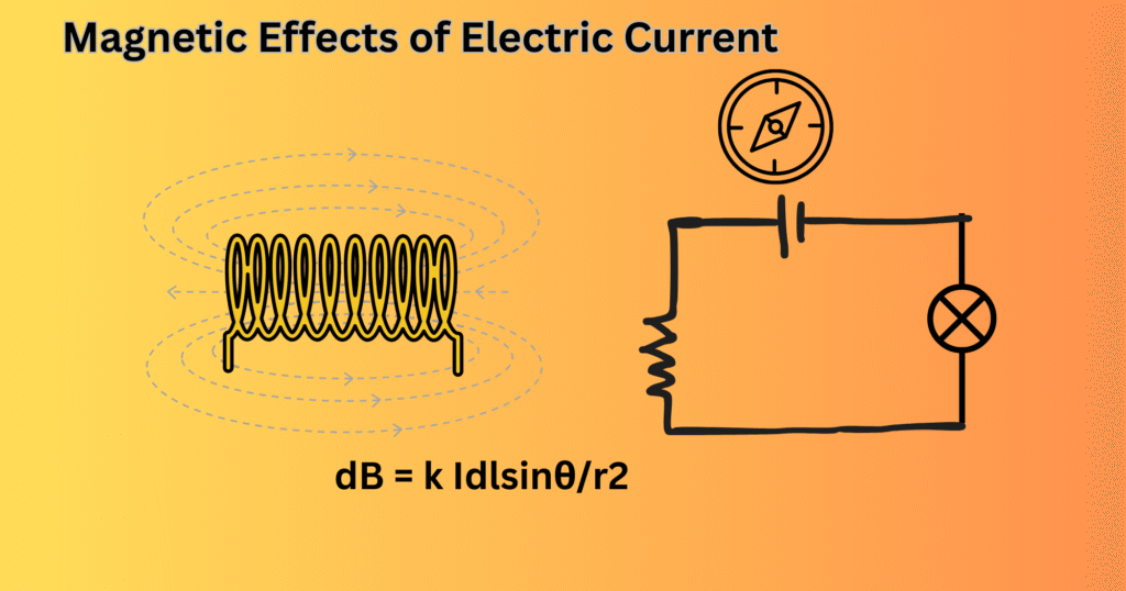
Jean Baptiste Biot and Felix Savart, combinedly gave a formula for the magnetic flux density at a point, produced by the neighbouring current-carrying conductor. They came to a conclusion that the magnetic flux density (dB) is directly proportional to the small length (dl) of the current element and the current through the conductor. If (θ) is the respective angle between the small length and the current flowing (I), then mathematically it is given as,
dB = k Idlsinθ/r2 [Equation 1]
Here k is the proportionality constant which is equal to μ0/4π and μ0 is called the permeability of the free space.
This equation shows that the magnetic field strength decreases with distance from the wire. The field lines form concentric circles around the wire, with their direction determined by the right-hand thumb rule.
Magnetic Field at the Center of a Circular Current Loop
Whenever a current is made to flow along a circular loop, the magnetic field is generated at its center. The field is given by:
B=μ0I/2R [Equation 2]
where R is the radius of the loop. From [Equation 2] we can say that the field at the center is directly proportional to the current and inversely proportional to the radius of the loop. If there are N no. of turns turns in the coil, the field will be:
B = μ0NI/2R [Equation 3]
Circular loops can produce strong and uniform magnetic fields and are used in devices like galvanometers and MRI machines.
Magnetic Field Inside a Solenoid B = μ₀nI and in a Toroid
A solenoid is a coil of wire with many turns. It produces a nearly uniform magnetic field inside the coil, when current flows through it. The magnetic field inside an ideal solenoid is:
B=μ0nI [Equation 4]
where n=N/L is the number of turns per unit length.
A toroid is also a solenoid but is bent into a circular shape. Thus, the magnetic field produced remains confined inside the core. The field inside a toroid is:
B = μ0NI/2πr [Equation 5]
Solenoids and toroids are used in inductors, transformers, and electromagnets.
Ampère’s Circuital Law and Applications to Symmetric Conductors
Ampère’s circuital law is a generalized form of Biot-Savart law that takes configuration symmetry like cylindrical, planar, toroidal or long straight conductors to produce a constant magnetic field. It states that the line integral of the magnetic field B around a closed path is equal to μ0 times the total current enclosed:
∮B⋅dl=μ0I [Equation 6]
While Biot-Savart law uses complex integrations, this law simplifies the calculations to some algebraic equations for those symmetric systems. Thus, it is more straightforward and desirable for the calculations.
Lorentz Force on a Moving Charge
When a charged particle moves inside electric and magnetic fields, it experiences a force which is called the Lorentz force in magnetostatics. It is given by
F=q(E+v×B) [Equation 7]
where q is the charge, E is the electric field, B is the magnetic field, and v is the velocity of the charged particle. The force is always parallel or antiparallel to electric field E which changes the velocity of the particle. Likewise, it is always perpendicular to the magnetic field B and the velocity, bringing out a circular or helical motion of the particle, keeping the velocity constant. The devices like cathode ray tubes, cyclotrons, and mass spectrometers operate under Lorentz’s force and hence has become the most important concept in electromagnetism and modern technology.
Force on a Current-Carrying Conductor
The interaction of moving charges with the magnetic field causes a mechanical force to a conductor carrying electric current. This is the same Lorentz force described above but here acting on a large number of electrons within the wire. It is given by,
F=I(L×B) [Equation 8]
where L is the length of the conductor with current I inside the magnetic field B. The direction of current and the magnetic field is given by the right-hand thumb rule. Electric motors are the suitable examples using this effect. Here, the coils carrying current are made to rotate by keeping inside magnetic fields. Loudspeakers, Railguns are other examples using this concept.
Fleming’s Left-Hand Rule: Predicting Force Direction
Fleming’s left-hand rule is applied in the case when a current-carrying conductor is placed inside a magnetic field to determine the direction of motion of the force due to the magnetic field. It states that to identify the direction of motion of force we have to stretch our thumb, fore finger, and middle finger perpendicular to each other. The fore finger represents the magnetic field direction, the middle finger gives the current direction, and the thumb gives the direction of motion of force.
Torque on a Current Loop: Principle of Electric Motors
Now, if a current-carrying loop is kept inside a magnetic field, a torque is detected that is responsible for rotating the loop. This is the working principle of electric motors. The coil is driven by the magnetic field provided. The torque induced is given by:
τ=nBIAsinθ [Equation 9]
where n is the number of turns in the loop, B is the magnetic field, I is the current, and A is the area of the loop.
Force Between Parallel Current-Carrying Wires and the Ampere
As now we already know that a wire carrying current produces a magnetic field around, now what happens if two wires are placed parallely? As both produce a magnetic field around them, both are influenced by each other exerting a force due to the field. If the current is made to flow in the same direction, the wires attract and conversely, if in opposite directions, they repel. The force per unit length between two parallel wires if kept at a distance d is:
F/L = μ0I1I2/2πd [Equation 10]
The SI unit of current was historically defined with the help of this force, which was derived as Ampere. One ampere is the constant current that is obtained by keeping two straight and parallel conductors of infinite length at a distance of 1 m in a vacuum. Thus, the force was obtained to be 2×10^−7 N per meter of length between them.
Therefore, the functional description of electric current before the modern definition on the basis of charge and time was provided by the parallel current concept.
Electromagnets, Solenoids, and Practical Applications
An electromagnet is the form of magnet that has combined application of electric and magnetic field. Here, a magnetic field is produced by an electric current. It is constructed by using a soft iron core coated with insulated wire. When current passes through the coil, it results in a magnetic field which makes the core magnetized. Thus, a powerful magnetic field is obtained by electromagnets. The permanent magnets can corrode or give reduced magnetic field while an electromagnet’s magnetism is desirable as it can be turned on and off by changing the current. This makes it more suitable and useful than the traditional magnets.
A solenoid is a long cylindrical coil of wire that has many turns, each of them carrying a current. The magnetic field inside a solenoid is steady (approximately) and parallel to its axis. THe field outside is relatively weak. The strength of the field depends on the number of turns, current, and length of the solenoid. When a soft iron core is inserted, the solenoid can act as an electromagnet. The direction of the magnetic field is obtained using the right-hand rule.
Some of their applications are:
- Electromagnets are used in cranes for lifting heavy iron, electric bells, relays, and MRI machines.
- Solenoids are used in electromagnetic switches, valves, and actuators.
- Strongly employed in electric motors, generators, and speakers, converting electrical energy into mechanical motion.
Measurement of Magnetic Field: Tesla Units and Instruments
The strength of the magnetic field is measured in tesla (T). Tesla is mathematically defined as one weber per square meter. Gauss can also be used as the unit of measurement for smaller fields. Devices like magnetometer and hall probe are used to measure the magnetic field accurately. Gaussmeters can measure the fluctuating magnetic field by detecting the induced emf. SQUIDs are the modern technologies that are highly sensitive and can measure very small fields which is very important in research and various applications.
Conclusion
Electric fields were already established as the renowned discoveries of the 1860s. However, their capacity to produce magnetic fields got equal importance and also became revolutionary findings. Their direction of flow and the forces produced by them on each other have several implications in modern technologies and engineering. The generalized laws and equations of magnetostatics are important methods for field calculations either a straight, cylindrical conductor or a loop. The contemporary technologies and machinery are the applications of electric and magnetic fields in combination. Electromagnets are replacing traditional magnets in many applications of medical fields and electricity generation. Thus, magnetostatics is a backbone of electromagnetism and modern technologies.
References
Purcell, E. M. (2013). Electricity and magnetism. Cambridge university press.
Panofsky, W. K., & Phillips, M. (2012). Classical electricity and magnetism. Courier Corporation.
Snelders, H. A. M. (1990). Oersted’s discovery of electromagnetism. Romanticism and the Sciences, 228-40.
Phillips, J. A., & Sanny, J. (2008). The Biot-Savart law: From infinitesimal to infinite. The Physics Teacher, 46(1), 44-47.
Cavalleri, G., Spavieri, G., & Spinelli, G. (1996). The ampere and biot-savart force laws. european Journal of Physics, 17(4), 205.
Al-Shaikhli, T., Ahmad, B., & Al-Taweel, M. (2019). The implementations and applications of ampere’s law to the theory of electromagnetic fields. Int. J. Adv. Sci. Technol, 28(8), 515-525.
Brain, M., & Looper, L. (2000). How electromagnets work. HowStuffWorks. HowStuffWorks. com, 1.
https://byjus.com/cbse-notes/cbse-class-10-science-notes-chapter-13-magnetic-effects-of-electric-current/