
The concept of electromagnetism lies on those imaginary lines of magnetic field. Thus, the total number of field lines entering and leaving a particular surface area is known as magnetic flux. The field lines also indicate the magnetic field strength. They resemble the electric field lines or strength through an area called electric flux and measure the flow of the magnetic field.
For better understanding, we can consider any flat surface that is kept inside a magnetic field. Of course, a number of field lines cross that flat surface which denote the magnetic flux. To make the maximum field lines to cross the surface, it should be placed directly, facing toward the field. That means, we can obtain maximum flux by placing the surface perpendicular to the field. Similarly, the result is reversed or minimum, if the surface is placed parallel to the field lines.
Mathematically, magnetic flux is represented by the Greek letter Φ (phi). It needs three important quantities for calculation: the magnetic field (B), the surface area (A), and the angle (θ) between them. Electromagnetism shows the transfer of energy to a mechanical work which requires the thorough study of magnetic flux and electric current in the systems like motors and generators.
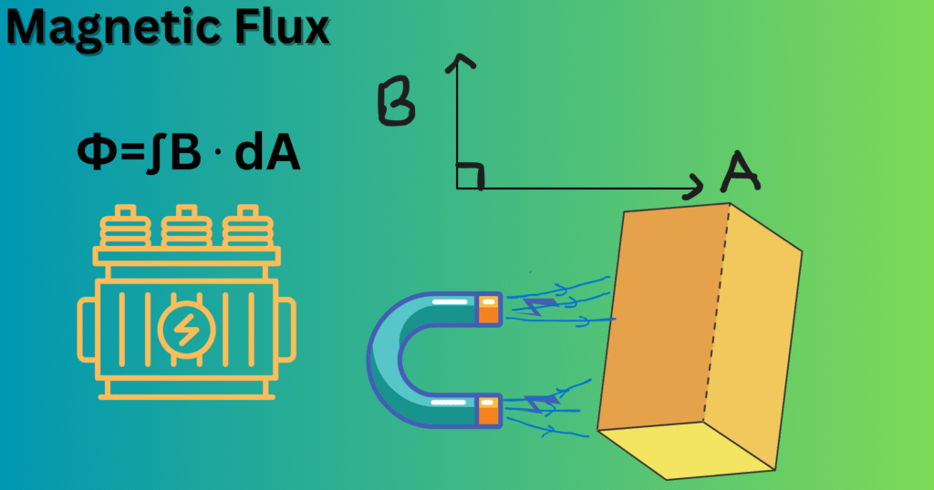
Formula and Units: Φ = ∫ B ⋅ dA (Weber, V·s, T·m²)
In simple way, magnetic flux is calculated as:
Φ=∫B⋅dA [Equation 1]
Here:
- B = magnetic flux density (Tesla, T)
- dA = small area element (m²)
- B ⋅ dA = is the dot product of the quantities taken only when B is perpendicular to A
For a uniform magnetic field and flat surface:
Φ=BAcosθ [Equation 2]
- A = area (m²)
- θ = angle between the magnetic field and the normal vector perpendicular to the surface.
Units
Magnetic flux is calculated in Weber (Wb) (in SI unit).
1 Wb = 1 Tesla × 1 m² = 1 V·s (volt-second).
In the CGS system, it is calculated as Maxwell (Mx), where:
1Wb = 10^8 Mx
This explains how a geometrical surface is linked to magnetic field strength and electricity.
Magnetic Flux vs Magnetic Flux Density (B)
Both can be heard as approximate quantities while a slight difference lies between them. It’s important to be clear about both: magnetic flux (Φ) and magnetic flux density (B):
- Magnetic Flux (Φ): It is the total magnetic field passing through the whole surface area. As described above, it depends on field strength, area, and the direction of the field and the area and is measured in Weber (Wb).
- Magnetic Flux Density (B): It means the density of the field lines per unit area. Thus, magnetic flux density means the presence of field lines per unit area. It measures how densely the magnetic field lines are present in the unit area, which is measured in Tesla (T).
B = Φ/A (when θ = 0°) [Equation 3]
Therefore, flux density counts how closely the field lines are spread while flux counts the total number of field lines.
Area, Orientation and cos θ Dependence in Uniform Fields
For stable and uniform magnetic fields, the angle between A and B highly affects the value of a flux, Φ=BAcosθ.
- If θ = 0° (A perpendicular to B): We get, cosθ = 1 → Φ = BA. Thus, maximum flux is obtained.
- If θ = 90° (A parallel to B): We get, cosθ = 0 → Φ = 0. Thus, no flux is obtained.
- θ lies between 0° and 90°: Partial flux may be obtained, depending upon the cosine of the angle..
Hence, we can say that the magnetic flux is directional that depends upon the angle between B and the surface area’s normal vector (not the surface area itself).
Magnetic Flux Through Non-Uniform Fields (Surface Integrals)
If the magnetic field is not uniform or the surface area is curved then the integral over the surface area is applied to find the total flux.
Φ=∫SB⋅dA [Equation 4]
Here, the surface S is now divided into small area elements and the flux over all those elements is summed. This method is used in complex problems, like flux through spheres, cylinders, or infinitesimal areas.
Gauss’s Law for Magnetism: Net Flux Through a Closed Surface is Zero
Among the four Maxwell equations, one condition is for the closed surface where the net magnetic flux is zero.
∮SB⋅dA=0 [Equation 5]
This is called the Gauss’s Law for Magnetism. This is because, unlike electric charges, magnetic poles always appear in pairs. Monopoles for magnets are impossible or never obtained. Therefore, magnetic field lines always form closed loops. In simple words, if we draw a closed surface around any object (like a sphere), the number of magnetic field lines entering the surface is exactly equal to the number leaving it. So, no matter what may be the shape of the surface, the total incoming magnetic field lines cancel the outgoing lines and result as zero.
Faraday’s Law: Induced EMF from Changing Magnetic Flux
Faraday’s law connects magnetic flux to the electricity and states mathematically as:
E=−dΦ/dt [Equation 6]
Here:
- 𝓔 = induced emf (volts)
- dΦ/dt = rate of change of flux
This means that when magnetic flux through a circuit changes, an emf is induced which gives an induced current. The negative sign shows that the induced current is in the direction opposite to the change in flux. The application of Faraday’s law is diverse like generators, transformers, induction cooktops, magnetic induction charging systems etc.
Magnetic Flux Linkage NΦ in Coils and Transformers
A coil having N turns also has flux linked with each turn which is given as,
Flux linkage = NΦ
Transformers are based on this concept. Other devices like inductors and electrical machines also rely on the magnetic flux linkage. Thus induced emf is given as,
E=−NdΦ/dt [Equation 7]
From the above relation we can see a direct relationship between the number of turns and the induced emf i.e., if the number of turns is increased we can get high induced voltage. This is the reason for using thousands of coils in transformers.
Measuring Magnetic Flux: Fluxmeters, Search Coils and Hall Sensors
Flux can also be measured by using certain devices. Some of them are given below:
- Fluxmeter: It can directly measure the total magnetic flux by using a coil connected to a ballistic galvanometer.
- Search Coil: It is a coil of wire which can measure the changing flux by measuring the induced emf.
- Hall Sensor: Hall effect is used by Hall Sensors to measure flux density (B). The magnetic flux can be derived from the flux density.
These tools are used in laboratories, electrical machine testing, and material studies.
Calculating Flux in Common Geometries: Loop, Solenoid and Toroid
- Circular Loop in uniform B:
Φ = BAcosθ, where A=πr^2
- Solenoid (length l, N turns, current I):
Magnetic field inside:
B=μ0N/l I [Equation 8]
Flux through each turn: Φ=BA
Total flux linkage = NΦ.
- Toroid:
Magnetic field inside:
B = μ0 NI/2πr [Equation 9]
Flux = BA, where A is the cross-sectional area of the toroid.
Magnetic Flux in Electric Machines: Generators, Motors and Inductors
Almost all the electrical systems count magnetic flux for the functioning of the system. It plays an unseen role for the conversion or transfer of electrical energy.
- Generators: In a generator, coils of wire keep rotating continuously inside a magnetic field. As they rotate, the amount of magnetic flux through the coils also keeps changing. Thus, Faraday’s law acts here as the change in flux induces an electromotive force (emf). The induced emf also produces a current and hence electricity is generated. In this way electrical energy is generated by the power houses for homes and industries.
- Motors: Motors act conversely to the generators. When current flows through coils inside a magnetic field, a force is produced. This force creates torque that rotates the coil. Thus, magnetic flux is also able to convert electrical energy into mechanical motion.
- Inductors: An inductor stores energy in the magnetic field created around its coil when current flows through it. The energy can be released later. This process is used in circuits for filtering, energy storage, and voltage regulation.
In summary, no electrical machines can make the transfer of energy without magnetic flux.
Flux Leakage, Core Saturation and Magnetic Circuits
Magnetic flux may not always have a perfect passage through a surface. In practice, situations like flux leakage and core saturation may arise. Thus efficient magnetic circuits must be designed.
- Flux Leakage
In transformers, motors, and other devices, the magnetic flux is made to pass through a closed loop of an iron or steel core. However, some of the flux keeps missing into the surrounding air instead flowing through the core. This is called flux leakage. Leakage reduces the efficiency as less flux results in lesser electrical energy. To minimize the leakage laminated or closed-loop cores are used. - Core Saturation
Magnetic materials like iron have limited flux capacity. On increasing the current, flux increases but only to a certain extent. Beyond that extent the material cannot magnetize further. This is known as core saturation. When saturation occurs, more current causes little or no increase in flux. This results in losses, overheating, and distortion in devices. That’s why materials with high magnetic permeability are used. The operating point is also kept below saturation. - Magnetic Circuits
Magnetic circuits provide a proper guide to the magnetic flux where the core works as a conductor for flux, and the air gaps provide some resistance.
Practical Units and Conversions: Weber and Maxwell
- The Weber (Wb)
- Named after Wilhelm Eduard Weber, a German physicist.
- 1 Weber is the amount of magnetic flux obtained when a magnetic field of 1 Tesla is applied to an area of 1 square meter, perpendicular to the surface.
- In electrical terms, 1 Wb = 1 V·s (volt–second). This shows the relation between flux and induced emf.
- The Maxwell (Mx)
- Named after James Clerk Maxwell, Scottish Physicist.
- 1 Maxwell is defined as the magnetic flux obtained when a magnetic field of 1 Gauss is applied to an area of 1 square centimeter, perpendicular to the surface.
- 1 Wb = 10^8 Mx
Modern calculations are done in Weber. However, Maxwell has been used frequently in older textbooks and in international standards. Thus, the conversion techniques are very important.
Sign Conventions and Area-Vector Direction (Common Mistakes)
Remember that the area vector (A) is always chosen normal to the surface. The direction convention follows the right-hand rule for loops. Some of the common mistakes while taking angles and signs are as follows:
- Taking θ as angle between B and surface but the angle must be taken with the normal vector to the surface.
- For Faraday and Lenz’s law, the negative sign is significant. Ignoring it makes a blundering mistake.
- Flux can be both positive or negative depending on orientation, so keep it in mind..
Worked Examples and Practice Problems on Magnetic Flux
Problem 1:
Find flux for the square loop of side 0.2 m, which is placed inside a uniform magnetic field of 0.5 T, making angle 60° to the normal.
Solution:
Φ = BAcosθ = 0.5×(0.2^2)×cos60°
Φ = 0.5×0.04×0.5 = 0.01 Wb
Problem 2
Calculate the flux linkage for a solenoid carrying 2 A current, with 1000 turns, length 0.5 m and cross-sectional area 2 × 10⁻³ m².
Solution:
B = μ0 N/l I = 4π×10^−7×1000/0.5×2
B ≈ 5.03×10^−3 T
Flux = BA = 5.03×10^−3 × 2×10^−3 = 1.006×10^−5 Wb
Flux linkage = NΦ = 1000×1.006×10^−5 = 0.010 Wb⋅turn
Example 3
What will be the flux for a closed spherical surface in a uniform magnetic field ?
By Gauss’s law for magnetism:
Φnet=0
Practice Problems
- A circular loop of radius 0.1 m lies in a field of 0.2 T parallel to the plane. Find flux.
- A coil of 500 turns links 0.02 Wb flux. Calculate flux linkage.
- A transformer coil experiences a flux change of 0.05 Wb in 0.01 s. Find induced emf for 200 turns.
- A rectangular area of 0.3 m² is at 45° to a 0.1 T magnetic field. Find the flux.
Conclusion
Whenever, the importance of electricity and its conversion arise, the role of magnetic flux becomes of equal importance. No, electrical systems can be thought of without magnetic flux. Thus, it is a significant concept in electromagnetism. The number of field lines determines the strength of a magnetic field in a certain area. The proper understanding of the flux helps researchers, engineers and also the electricians to design, operate and test the electric systems. The machines like generators, motors, transformers also depend upon flux count for their operation. The units, their inter-conversions and proper difference between the flux and flux density should also be thoroughly studied for the broad understanding of magnetic flux.
References
Grant, I. S., & Phillips, W. R. (2013). Electromagnetism. John Wiley & Sons.
Belot, G. (1998). Understanding electromagnetism. The British Journal for the Philosophy of Science, 49(4), 531-555.
Giuliani, G. (2008). A general law for electromagnetic induction. Europhysics Letters, 81(6), 60002.
Guisasola, J., Zuza, K., & Almudi, J. M. (2013). An analysis of how electromagnetic induction and Faraday’s law are presented in general physics textbooks, focusing on learning difficulties. European Journal of Physics, 34(4), 1015.
https://www.examples.com/physics/units-of-magnetic-flux.html
https://www.electricalvolt.com/what-is-magnetic-flux-definition-properties/
https://www.geeksforgeeks.org/physics/magnetic-flux/