
Equilibrium of forces is one of the fundamental concepts of mechanics. We know that, in practice, various forces act on an object at rest or while in motion. If all the forces acting on that object are balanced, then the object either stays at rest or keeps moving continuously with constant velocity. This balanced state of an object is known as the equilibrium of forces. For example, a book lying on a table, the motion of fan blades, a person standing still on the ground, etc.
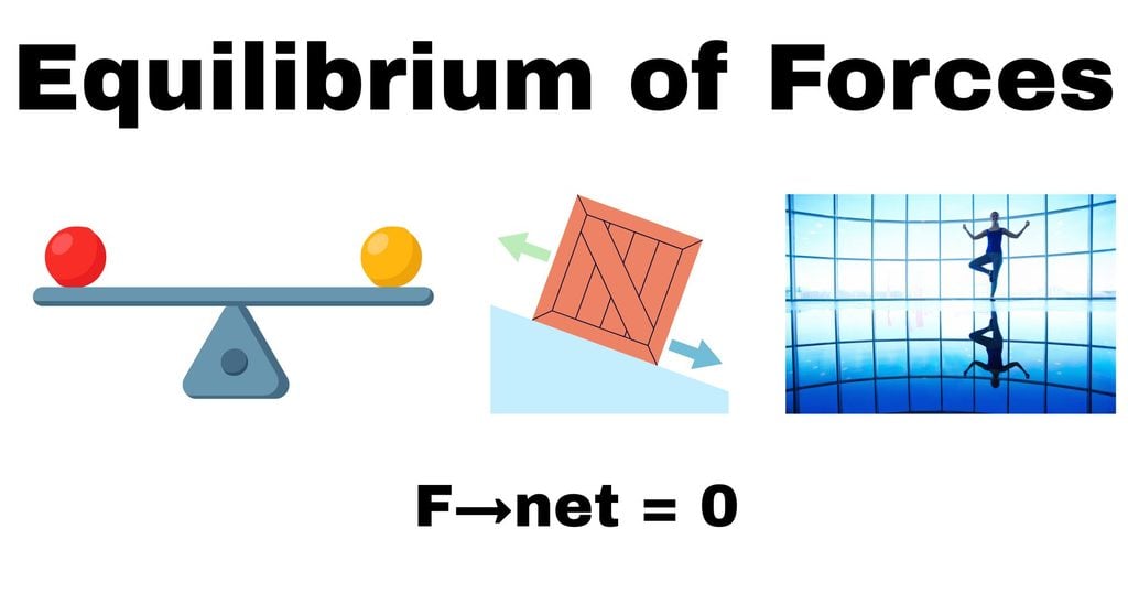
A force is defined as a factor or a quantity that brings a change in the state of a body. However, in equilibrium of forces, there are several forces acting on a body; still, the body experiences no net acceleration. This is because the net effect of forces cancels out, and hence the body remains balanced. The forces acting may be torque, tension, weight, reaction force, normal force, viscous force, moment, etc., but the body will be in complete mechanical equilibrium.
Understanding the concept of equilibrium is very important in fields like physics, engineering, architecture, etc. Many construction and design works by engineers and architects are done to obtain equilibrium under huge forces. Similarly, forces are well understood and analyzed in physics with the help of this principle.
What Is Equilibrium of Forces?
The word equilibrium means a balanced condition. In physics, we call an object in equilibrium when the net effect of all the forces acting on it produces no effect or acceleration on that object.
According to Newton’s second law of motion,
F→net = m a→ [Equation 1]
where:
- Fnet is the resultant or net force.
- m is the mass of the object.
- a is its acceleration.
For an object to have zero acceleration,
a→ = 0
Therefore,
F→net = 0
This is the fundamental condition for translational equilibrium.
Hence, in translational equilibrium, the object either remains at rest or continues to move in a straight line with constant velocity.
Static and Dynamic Equilibrium
On the basis of an object’s state, equilibrium is also of two types.
-Static Equilibrium
An object is said to be in static equilibrium if it continues to be at rest with respect to its surroundings.
For example, a book resting on a table is acted on by a gravitational force in the downward direction, while the normal reaction from the table will be acting in the upward direction. Thus, the upward and downward forces balance each other, and the net force will be zero. In this case,
N = mg [Equation 2]
Where,
- N = normal reaction
- mg = weight of the book.
-Dynamic Equilibrium
An object is said to be in a dynamic equilibrium if it continues to be in motion, with constant velocity, whatever be the forces acting on it.
For example, a car moving with a uniform speed on a straight road will have a driving force which is balanced by air resistance and friction.
Thus,
Fdriving = Fresistance
Hence, we can understand this case as a condition when all forces are acting, but their vector sum will be zero and offer no net force to the body.
Translational and Rotational Equilibrium
Equilibrium involves more than balancing forces. A body may experience zero net force but still rotate if the forces produce a turning effect.
Therefore, complete equilibrium requires both:
- Zero resultant force.
- Zero resultant torque about any point.
These conditions are essential to understand the balanced condition of extended bodies like beams, ladders, bridges, and other rigid structures.
Conditions for Equilibrium
For a body to remain in complete mechanical equilibrium, the total force and total turning effect acting on it must both vanish.
First Condition of Equilibrium
The first condition is that the vector sum of all external forces acting on a body must be zero.
Mathematically,
ΣF→ = 0 [Equation 3]
For a two-dimensional system, this can be expressed in vertical and horizontal components.
∑Fx = 0 [Equation 3a]
and
∑Fy = 0 [Equation 3b]
Here:
- ∑Fx represents the algebraic sum of horizontal forces.
- ∑Fy represents the algebraic sum of vertical forces.
If both sums are zero, the body has no translational acceleration.
Example of the First Condition
For example, if a boy pulls a box horizontally by a force of 50 N toward the right, friction will be acting towards the left.
For the box to remain in equilibrium,
Fpull − Ffriction = 0 [Equation 4]
Therefore,
50 − Ffriction= 0
Hence, a frictional force of 50 N must be acting towards the left.
Second Condition of Equilibrium
The second condition is that the algebraic sum of all torques acting on a body must be zero.
∑τ = 0 [Equation 5]
Torque produces a turning effect on a body remaining fixed about a pivot.
For a force F at a perpendicular distance r⊥ from a pivot,
τ = Fr⊥ [Equation 6]
If the force makes an angle θ with the position vector, the torque will be:
τ = rFsinθ [Equation 7]
The condition for rotational equilibrium is,
∑τclockwise = ∑τanticlockwise [Equation 8]
Both conditions are equally necessary in rotational motion because if there is not only one force acting from a fixed point (torque) but two forces are acting at different points, then another twisting force called a couple is produced. Thus, both equilibrium conditions complete the concept of rotational equilibrium.
For a rigid body in a plane, the equilibrium equations will be:
∑Fx = 0
∑Fy = 0
∑τ = 0
These three equations are widely used to solve ladder, beam, or any support-involving problems.
Equilibrium in Three Dimensions
For a body in three-dimensional space, the conditions of equilibrium are:
∑Fx = 0, ∑Fy = 0, ∑Fz = 0
and
∑τx = 0, ∑τy = 0, ∑τz ,= 0
There are therefore six independent scalar equilibrium equations for a rigid body in three dimensions.
Principle of Moments
As expressed in equation (8), the principle of moments states that the net clockwise moment about a fixed point must be equal to the net anticlockwise moment, to remain in rotational equilibrium.
Mathematically, this is equivalent to the condition
∑τ = 0
Moment of a Force
The moment of a force is its turning effect about a point.
It is given by
τ = Fr⊥
where:
- τ is the moment of the force.
- F is the magnitude of the force.
- r⊥ is the length of the moment arm.
If the force and the position angle are lying at a certain angle θ, then
τ = rFsinθ
The moment is maximum when
θ = 90°
because
sin90° = 1
If the line of action of the force passes through the pivot, the moment will be zero.
Clockwise and Anticlockwise Moments
A force can make an object turn clockwise or anticlockwise, and the sign is taken opposite for each other.
Thus, we can write:
τclockwise – τanticlockwise = 0
Applications of the Principle of Moments
The principle of moments is used in:
- Seesaws and playground equipment.
- Spanners and wrenches.
- Levers and mechanical tools.
- Beam bridges.
- Crane arms.
- Balancing scales.
- Door handles.
- Wheelbarrows.
- Structural support.
The principle helps determine unknown forces, distances, and loads required for balance.
Resultant Force and Resultant Torque
When several forces act on a body, they can be replaced mathematically by a single resultant force and, where necessary, a resultant torque.
Resultant Force
The vector sum of all forces can be called a common force acting on a body, called the resultant force.
R→ = ∑F→ [Equation 9 ]
For two forces F1→ and F2→,
R→ = F1→ + F2→
Resultant Force in One Dimension
If two forces are acting oppositely in the same straight line, the resultant is found by subtraction.
For example, if a force of 70 N is acting towards the right and a force of 40 N is acting towards the left, we can take the greater force as positive. So, taking right as positive,
R=70−40
R=30 N
Hence, the resultant force will be 30 N toward the right.
In one dimension, the two equal and opposite forces have zero resultant.
Resultant Force in Two Dimensions
For forces acting in two dimensions, we take horizontal and vertical components.
For resultant components being Rx and Ry along the x and y axes respectively, then
R = √Rx2+ Ry2 [Equation 10]
The direction of the resultant is
tanθ = Ry/Rx [Equation 11]
The correct quadrant must be considered when determining the direction.
Resultant Torque
The resultant torque is the vector sum of the torques produced by all forces about a chosen point.
τ→net = ∑τ→ [Equation 12]
For planar systems, clockwise and anticlockwise torques are given opposite signs.
Resultant Force and Torque in Equilibrium
For complete equilibrium,
R→ = 0
and
τ→net = 0
A body with zero resultant force but nonzero resultant torque can rotate.
A body with zero resultant torque but nonzero resultant force can translate or accelerate.
Both must be zero for complete equilibrium.
Force-Couple Systems
In some cases, a complicated system of forces can be replaced by:
- A single resultant force.
- A couple or resultant torque.
A couple has two forces acting along different lines of action that are equal, opposite, and parallel.
The net force of a couple is zero, but its net torque is generally nonzero.
If the perpendicular separation between the forces F is d, the moment of the couple is
τ = Fd
A couple always produces pure rotation and no translation.
Examples include:
- Turning a steering wheel.
- Opening a tightly closed bottle cap.
- Using two hands to rotate a knob.
- Turning a screwdriver.
Coplanar Forces and Vector Triangles
Coplanar forces have their lines of action in the same plane.
All two-dimensional objects like beams, ladders, or support systems involve coplanar forces in mechanics.
Coplanar forces may be:
- Collinear.
- Concurrent.
- Parallel.
- Non-concurrent.
Collinear Forces
Collinear forces are always lying on the same straight line.
For example, two people may pull a box in opposite directions along a horizontal line.
If the forces are equal and opposite,
F1 = F2
then
R = F1 − F2
The forces are balanced.
Concurrent Forces
The lines of action of concurrent forces share a common point.
For example, several ropes attached to a ring may exert forces on the ring. If the ring remains stationary, the forces must balance.
Concurrent force systems are often analyzed using vector addition and force triangles.
Parallel Forces
Parallel forces have parallel lines of action, no matter what directions they have.
Examples include:
- The weight of a beam acting downward.
- Upward reactions at the supports of a bridge.
- Forces acting on a loaded platform.
Parallel forces can produce both a resultant force and a resultant moment.
Vector Addition of Forces
Forces are added using vector methods because they possess both magnitude and direction.
Suppose two forces A→ and B→ act at an angle θ. The magnitude of their resultant is
R = √A2+B2+2ABcosθ [Equation 13]
If the forces are perpendicular,
θ = 90°
and
R = √A2+B2
Vector Triangle Method
The vector triangle method is a graphical technique for adding two vectors.
A vector triangle is constructed by choosing one force and draw its vector. Now, from its head, the second vector is drawn, and to the head of the second one, the tail of the first one. Their joining line is their resultant.
For the three vectors forming a closed triangle, we call these three forces to be in equilibrium.
Thus, for three forces in equilibrium,
F1→ + F2→ + F3→ = 0
This is sometimes called the triangle of forces.
Triangle of Forces
The triangle of forces states that if three forces acting at a point keep the point in equilibrium, they can be represented in magnitude and direction by the three sides of a closed triangle taken in order.
Suppose a small ring is being pulled by three strings; if the ring remains at rest, the three tension forces form a closed vector triangle.
This method is useful when the magnitudes or directions of forces are unknown.
Free-Body Diagrams and Equilibrium
A free-body diagram is commonly written in an abbreviated form as FBD. A FBD is a diagram that shows all external forces acting on an isolated object. An object is generally represented by a box, circle, dot, or a simple shape rather than its exact picture, and all the forces acting on it are given arrows according to their direction. Hence, it simplifies understanding forces while solving problems.
Each arrow should indicate:
- The name of the force.
- Its direction.
- Its point of application, where relevant.
- Its magnitude, if known.
Common Forces in Free-Body Diagrams
-Weight
Weight is the pull of gravitational force on a mass.
W = mg
It acts vertically downward near Earth’s surface.
-Normal Reaction
The normal reaction is the contact force exerted by a surface on an object.
It acts perpendicular to the contact surface.
For a stationary object on a horizontal surface with no other vertical forces,
N = mg
-Tension
Tension is a pulling force that is exerted on stretching objects like a stretched string, rope, or cable.
It acts along the length of the string away from the object.
-Friction
Friction is the force exerted by the surface in contact with the body that tries to oppose motion and acts parallel to the surface in contact.
For a body in equilibrium, static friction adjusts as needed up to its limiting value.
-Applied Force
An applied force is a push or pull experienced by an object exerted by external factors.
It may act horizontally, vertically, or at an angle.
-Air Resistance
Air resistance acts opposite to the object’s motion in air. It is noticeable when an object moves through the atmosphere.
Steps for Drawing a Free-Body Diagram
A useful procedure is:
- Identify the object being studied.
- Isolate it from its surroundings.
- Draw the object as a simple shape.
- Identify every external force acting on it.
- Draw arrows in the correct directions.
- Label each force clearly.
- Choose coordinate axes.
- Resolve angled forces into components if necessary.
- Apply the equilibrium equations.
Importance of Free-Body Diagrams
Free-body diagrams help students and engineers:
- Identify forces correctly.
- Avoid missing important forces.
- Distinguish internal and external forces.
- Resolve forces into components.
- Apply Newton’s laws.
- Calculate unknown reactions and tensions.
- Analyze complex mechanical systems.
A correctly drawn free-body diagram is often the first major step toward solving a mechanics problem.
Applications of Equilibrium of Forces
The several applications of principles of equilibrium are:
Buildings and Structural Engineering
Buildings must remain stable under large loads and hence must be strong and balanced with supports.
Forces may arise from:
- The weight of the structure.
- Occupants and furniture.
- Wind.
- Snow.
- Earthquakes.
- Attached equipment.
All these forces and moments will be acting on beams, columns, foundations, and joints.
To build a stable structure, the heavier loads are safely transmitted to the ground without translation, rotation, or collapse.
Bridges
Bridges also must support their own weight and various loads moving through them.
A simple beam bridge may have upward support reactions and downward loads.
For a bridge in static equilibrium,
∑Fy = 0
and
∑τ = 0
These equations help to find the magnitude of reactions at the supports.
For a uniform beam supported at both ends, its weight acts through its centre of gravity. Hence, the support reactions are given to balance the downward load.
Cranes and Lifting Machines
Cranes also lift heavy loads using beams, cables, pulleys, and counterweights. The load produces a turning effect about the crane’s base. Counterweights and support reactions help maintain stability.
The equilibrium and principle of moments should be considered to:
- Safe load limits.
- Counterweight requirements.
- Cable tensions.
- Support reactions.
- Overturning tendencies.
Ladders
A ladder leaning against a wall should also attain equilibrium according to the two-dimensional equilibrium condition.
The various forces acting on it are:
- Its weight.
- The normal reaction from the floor.
- Friction at the floor.
- The normal reaction from the wall.
- Friction at the wall, if the wall is rough.
Seesaws and Balancing Scales
A seesaw is based on the principle of moments, i.e., for two forces F1 and F2 acting at distances d1 and d2 respectively from the pivot,
F1d1 = F2d2
A lightweight on the other side can balance a heavier weight if it is kept farther from the pivot.
Balancing scales work on a similar principle. Equal moments produce rotational equilibrium.
Wheelbarrows
A wheelbarrow is a lever with the wheel acting as the pivot.
The load produces a moment about the wheel. In opposition, the lifting force applied at the handles produces an opposite moment.
The effort required depends on:
- The load’s weight.
- The distance of the load from the wheel.
- The distance between the handles and the wheel.
Human Body and Posture
The human body maintains balance through the interaction of gravitational forces, muscle forces, and contact reactions.
When a person stands still, the net force and net torque must be approximately zero.
Muscles continuously adjust joint forces to maintain posture.
For example, when a person bends forward, the muscles of the back produce torque to balance the turning effect of the upper body’s weight.
Mechanical Tools
Tools such as spanners, screwdrivers, pliers, and levers use force and torque principles, i.e.,,
τ = Fr⊥
Hence, the moment arm is kept longer to achieve greater turning force.
Aircraft and Ships
Aircraft and ships must maintain balance during operation.
For an aircraft, forces such as lift, weight, thrust, and drag affect its motion.
During steady, level flight, lift approximately balances weight and thrust balances drag.
For ships, buoyant force must balance weight when the ship floats at rest.
These examples show how equilibrium principles are important in transportation and design.
Solved Problems on Equilibrium of Forces
The following examples illustrate how to apply the conditions of equilibrium.
Problem 1: A Book Resting on a Table
A book of mass 5 kg rests on a horizontal table. Calculate the normal reaction exerted by the table. Take
g=9.8 m/s2
Solution
The forces acting on the book are:
- Weight downward.
- Normal reaction upward.
The weight is
W = mg
Substituting,
W = 5×9.8
W=49 N
For vertical equilibrium,
∑Fy = 0
N−W = 0
Therefore,
N = W
N = 49 N
Hence, the normal reaction is 49 N upward.
Problem 2: Two Opposing Horizontal Forces
A box is pulled by a force of 120 N toward the right. Friction acts toward the left. If the box is in equilibrium, determine the frictional force.
Solution
For horizontal equilibrium,
∑Fx = 0
Taking right as positive,
120−Ff = 0
Therefore,
Ff = 120 N
Therefore, the frictional force is 120 N toward the left.
Problem 3: Balancing a Beam
A uniform horizontal beam of length 6 m and weighing 200 N is in equilibrium with supports at both ends. What will be the reaction force at each support?
Solution
Since the beam is uniform, we can take the weight at the centre.
The centre is
6/2 = 3 m
from either end.
Let the reactions at the left and right supports be RA and RB.
The vertical equilibrium condition gives
RA + RB − 200 = 0
Thus,
RA + RB = 200
Taking moments about the left support,
RB(6) − 200(3) = 0
6RB = 600
RB = 100 N
Therefore,
RA = 200 − 100
RA = 100 N
Hence,
RA = RB = 100 N
Hence, each support provides an upward reaction of 100 N
Problem 4: Two Perpendicular Forces
Suppose two perpendicular forces of 6 N and 8 N act on a particle. What is the magnitude of the third force that keeps the particle in equilibrium?
Solution
The resultant of the two perpendicular forces is
R = √62+82
R =√36+64
R =√100
R=10 N
The third force must be equal in magnitude and opposite in direction to the resultant.
Therefore,
F3=10 N
Problem 5: Two support systems sharing equal loads
A signboard of weight 300 N is suspended with the help of two vertical cables. If the cables carry equal loads, find the tension in each cable.
Solution
Let us denote the tension in each cable by T,
Since the signboard is in vertical equilibrium,
T+T−300 = 0
2T = 300
T = 300/2
T=150 N
Hence, each cable supports a tension of 150 N.
Problem 6: Equilibrium of three forces
Suppose a ring is acted upon by three forces. The two forces are perpendicular to each other with magnitudes 9 N and 12 N. Find the magnitude and direction of a third force required to maintain equilibrium.
Solution
The resultant force will be,
R = √92+122
R =√81+144
R = √225
R=15 N
The third force must have magnitude 15 N and act opposite to the resultant.
To find the angle of the resultant relative to the 9 N force,
tanθ = 12/9
tanθ = 1.333
θ ≈ 53.1°
Therefore, the balancing force must be acting approximately 53.1° below the negative direction of the 9 N force.
Conclusion
Forces are the foundation of physics, and the equilibrium of forces is a principle of classical mechanics and the natural world. It explains inertia and hence Newton’s laws of motion. The balanced condition is an important condition for the structural world. It tells how an object can remain in a steady state of rest or motion, keeping all effects of forces zero.
The first condition of equilibrium is for translational equilibrium and says that the resultant force must be zero:
∑F→ = 0
For a body to remain in complete mechanical equilibrium, the resultant torque must also be zero:
∑τ→ = 0
For two-dimensional systems, these conditions will be:
∑Fx = 0, ∑Fy = 0 and ∑τ = 0
The principle of moments helps analyze rotational balance, while vector methods and force triangles are useful for understanding systems of coplanar forces. Free-body diagrams help us to clearly visualize the nature of forces and apply equations as required.
Not only the principles of physics, but engineering also relies on the principle of equilibrium of forces. The construction of huge projects like buildings, transport systems, bridges, etc., fully relies on equilibrium principles. The lack of equilibrium can cause massive destruction. Even the physics of human body posture relies on maintaining equilibrium. Hence, it is not only a theoretical concept but a concept of nature that requires equilibrium to survive.
References
- Mittelstedt, C. (2026). Force Systems and Equilibrium. In Engineering Mechanics 1: Statics (pp. 15-55). Berlin, Heidelberg: Springer Berlin Heidelberg.
- Clark, J. F. (1887). Equilibrium, the Controlling Force in Nature. Hall’s Journal of Health, 34(8), 182.
- Synge, J. L. (2011). Principles of mechanics. Read Books Ltd.
- Rapcsák, T. (2003). Mechanical equilibrium and equilibrium systems. In Equilibrium Problems and Variational Models (pp. 379-399). Boston, MA: Springer US.
- Rouche, N., Habets, P., & Laloy, M. (1977). Stability of a mechanical equilibrium. In Stability Theory by Liapunov’s Direct Method (pp. 97-127). New York, NY: Springer New York.
- https://modern-physics.org/equilibrium/
- https://www.aakash.ac.in/important-concepts/physics/equilibrium-of-forces
- https://www.grc.nasa.gov/www/k-12/airplane/equilib.html
