
The term “taper” indicates a geometric shape characterized by a gradual reduction in cross-sectional area. A tapered end is a frequent feature of machining tools, which facilitates tool changes.

What is Taper?
- A taper is a consistent decrease in a part’s diameter or cross-section. The end product of applying a taper frequently has a cone-like shape. The cross-section of the cone example tapers to a point. A taper tool, on the other hand, simply causes the part’s cross-section to taper from broader to narrower.
- A machine taper is a device that fastens cutting tools and tool holders to a machine’s spindle head.
- Machines such as milling machines, lathes, and portable and tabletop drills all use taper. By making it simple for technicians to find the taper inside the machine head, the male taper helps facilitate tool changes in machinery. It is also less necessary to use a chuck when employing a tapered interface because chucks require time-consuming manual adjustment using a screw mechanism.
- The machine head’s taper angle and the taper tool’s taper angle coincide to enhance friction between the two components. The taper may be held in place during light-duty milling by friction alone. A key and notch are utilized in heavy machining, nevertheless, to stop the tapered tool from spinning inside the machine head.
- The interface between the cutting tool and the machine head (lathe, milling, or drilling) is a taper tool. The taper’s functions include holding the tool in position and facilitating fast tool changes. The fact that taper allows large machine heads to handle both large and small tools is another reason for their utilization. On the other hand, because a screw mechanism is required to tighten the chuck, machines with a single chuck may take a long time to adjust when switching from a large to a small tool.
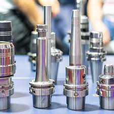
[Image source: https://www.xometry.com/resources/machining/taper/]
Types of Tapers
The eight different kinds of tapered tools that are currently in use all operate according to the same theory. The taper tools differ from one another in terms of size and self-holding versus quick-release features. We go over each of these taper below:
- Jarno
- Made of 52100 steel, all Jarno tapers have a taper-per-foot ratio of 0.60″.
- Jarno tapered tools are employed in die-sinking machines, profiling, and as headstock and tailstock spindles on lathes.
- With the large end spanning from 0.25–2.50″ and the small end from 0.20–2.00″, Jarno taper comes in 19 different sizes.
- Jacobs
- Because of its self-holding taper, a Jacobs tapered tool doesn’t need a drawbar.
- The size of the taper will affect the Jacobs taper ratio. Because it can hold itself, the Jacobs taper is suited for light-duty applications.
- Drill chucks are nearly exclusively fastened to arbors using Jacobs tapered tools.
- There are nine sizes available for the Jacobs taper, and each size is denoted by JT + a number. JT0, JT2 short, JT2, and JT6 are a few examples.
- Brown and Sharpe
- The standard taper ratio for Brown and Sharpe tapered tools is 0.50″ per foot.
- The Jarno taper and the Brown and Sharpe taper are both composed of 52100 steel. For drill bits, reamers, end mill holders, and collets, older tooling machines are most likely to use Brown and Sharpe tapers.
- There are eighteen Brown and Sharpe taper, with a big end size ranging from 0.24 to 3.42″ and a small end ranging from 0.20 to 3.00″.
- Morse
- A tapered spindle used for tool mounting is called a Morse tapered tool.
- Reamers, drill bits, mill holds, collets, and lathe centers are just a few of the many uses for Morse tapers. The Morse taper comes in eight diameters, ranging from MT0 to MT7, and is self-holding.
- The taper of each of the various Morse sizes is roughly 0.625″ per foot. If using a drawbar is necessary, the self-holding Morse taper end must be adjusted.
- B Tapers
- Machining centers, heavy-duty milling machines, high-precision machining, and lathes are among the applications for type B tapers.
- Eight diameters are available for the B taper; the large end ranges from 0.25 to 0.94 and the small end from 0.230 to 0.84″.
- HSK Tapers
- HSK taper ratios are 1 in 10, or 1.20″ per foot, and they are hollow and short.
- The machine’s spindle is kept near to the workpiece by the short length of HSK taper tools.
- Depending on the version, HSK taper tools can be used for a variety of tasks, such as lathes, milling, and grinding.
- The six categories, HSK-A through HSK-F, include the 36 HSK sizes.
- NMTB Taper Family
- These taper sizes are NMTB-25, 30, 35, 40, 45, 50, and 60. The taper ratio for these tapers is 3.50″ per foot.
- The NMTB taper was created especially to be used with NMTB spindles, which fasten the shank in the spindle with a drawbar.
- For heavy-duty applications, NMTB tapers have a single flange with two keyways.
- R8 Taper
- Another name for the R8 taper is the M1TR taper.
- They are fastened in their spindles by a drawbar. This taper has a straight collet end that is secured in place with a drawbar.
- There are twenty-six sizes of R8 taper tools, ranging from 1/16″ to ⅞” in 1/32″ steps.
Besides these, there are other two types of tapers:
- Self-Releasing Tapers
- Steep tapers, another name for self-releasing tapers, are made with an inclined angle to facilitate the simple and dependable disengagement or removal of mated components.
- When necessary, these tapers are designed expressly to make it easier to separate interlocking elements.
- The main uses for these tapers are assembly and alignment.
- The shape of the self-releasing taper makes it easy to separate components when they are properly aligned. This functionality is especially useful in tool holders and machine tool spindles, for example, when rapid assembly and disassembly are necessary.
- Self-Holding Tapers
- Self-holding taper angles are those whose geometry produces a wedging action that keeps them firmly in place when seated correctly.
- These taper tips are intended to offer stability and resistance to movement, in contrast to self-releasing ones.
- Self-holding tapers are frequently employed in tool shanks and collets, for example, where a solid and dependable fit is required.
- Stability and safety are provided by the taper’s wedging action, which makes sure the parts don’t accidently separate while in use.
Applications of Taper
- Using rotary cutters, milling machines are a kind of technology that removes material from an object. This material is removed by holding the workpieces and cutting the material in various designs, such as tapering, with cylindrical tools.
- Lathes eliminate extra or unnecessary material from products in a manner akin to that of milling machines. Lathes, on the other hand, rotate the workpiece horizontally to remove superfluous material instead of maintaining it still, unlike milling machines.
- Tapered tools are frequently used with pedestal drills to allow for fast drill bit changes. A larger variety of drill bit sizes may be used with pillar drills thanks to the usage of tapers, which is not possible with a normal chuck.
Taper Turning
The machining technique known as “taper turning” is used in engineering and manufacturing to gradually reduce a cylindrical workpiece’s diameter from one end to the other, giving it a conical or tapered shape. This is accomplished by angling the cutting tool with respect to the workpiece’s axis, which results in a consistent change in diameter along the workpiece’s length. Depending on the required taper direction, taper turning can be applied to either the interior or external surfaces of the workpiece.
Many industries use this machining process for a variety of reasons, from enhancing appearance and usefulness to making sure assemblies fit and align correctly.
- A machining technique called taper turning is used in engineering and manufacturing to properly form angled or conical surfaces on workpieces. Reducing a cylindrical workpiece’s diameter gradually from one end to the other is the goal. A tapered shape is produced by angling the cutting tool with respect to the axis of the workpiece. With advantages including improved load-bearing capacity, better alignment, and self-locking capabilities, these tapered parts are regarded for their capability to boost fit and functionality in assemblies. Furthermore, tapering can lower component weight without compromising structural integrity. Furthermore, by meeting strict tolerances and quality standards, precise taper turning lessens the need for extra post-machining procedures.
- A lathe is usually used for taper turning. A cylindrical workpiece is first secured in the lathe’s chuck, which acts as a clamping mechanism, or between centers, where it is supported at both ends and stays out of contact with the chuck. The axis of interest for the taper-turning process is the workpiece’s axis of rotation, which is made possible by this arrangement. A cutting tool is positioned to engage with the workpiece and mounted on the tool post of the lathe. The appropriate taper angle is determined by adjusting the cutting tool at an angle with respect to the workpiece axis in order to achieve the taper. The cutting tool comes into contact with the rotating workpiece after it has reached the desired speed of rotation. It gradually eliminates material as it goes along the length of the workpiece, reducing its diameter and creating the correct taper. The exact, intended dimensions and angle of the taper are guaranteed by careful control of the tool’s angle and feed rate.
- The size of the workpiece and the intended taper angle will determine how long it takes to complete a taper turning operation.
- Because more material needs to be removed to generate the taper, larger workpieces typically take longer. More extensive material removal may be required due to steeper taper angles, which will add to the time required. The kind of material being machined can also affect how long it takes to complete a task; certain materials need slower machining rates because they are more difficult to cut. Other things to think about are the cutting tool’s capabilities and design, the machining equipment being used, tool wear and the necessity for tool changes, the geometry and complexity of the taper, the number of passes needed to turn the taper, and the expertise.
- Metals, which include a broad variety of materials such alloy steel, cast iron, carbon steel, aluminum, stainless steel, copper, magnesium, zinc, and metal alloys, are the main materials utilized in the turning process. However, the procedure is not exclusive to metals. In addition, it can handle the machining of ceramics, composites, thermoplastics, thermosets, and plastic components. It is even possible to taper turn several kinds of wood, including both hardwoods and softwoods.
- High accuracy can be achieved with taper turning if a few crucial variables are properly taken into account and managed. The quality of the material being machined and the machining equipment being utilized are related to the precision of taper turning. To provide precise and consistent outcomes, modern, tightly-tolerated machinery is better suited. Accuracy is also greatly influenced by the selection and optimization of cutting parameters, such as feed rates and cutting speeds. Furthermore, the cutting tool’s quality and sharpness are crucial because dull or worn-out tools can introduce errors and uneven surface finishes. Additional criteria include operator competence and experience, as well as the accurate alignment of the workpiece and adequate configuration of the cutting tool.
- Among the major sectors that use taper turning a lot are the manufacturing, automotive, aerospace, and construction industries. Taper turning is used in general manufacturing to make a variety of components having tapered features, including wedges, tool handles, shafts, and pins. For these parts to fit into assemblies, offer structural support, or enhance operation, they frequently need to be precisely tapered.
- Taper turning is essential to the aerospace industry’s ability to produce airplane components. Tapered forms are commonly necessary for aircraft engine components, landing gear elements, and control surfaces in order to maximize aerodynamics, minimize weight, and guarantee correct alignment.
- Taper turning is also used in the automotive sector to manufacture axles, tie rods, and suspension parts. Tapered parts can improve the safety and performance of a vehicle.
- Taper turning is used in construction to make specialized parts for infrastructure projects, heavy machinery, and building constructions. The functionality and stability of construction machinery and buildings can be enhanced by tapered sections.
Methods of Taper Turning
- Tool Method
- A simple technique for turning short tapers on a lathe is the form tool approach.
- A broad-form tool with a straight cutting edge set at half the appropriate taper angle is used in this process.
- The workpiece takes on a tapered shape as the tool is fed straight into it.
- When the taper’s length is less than the tool’s cutting edge, this technique works especially well for shorter taper lengths. However, because the entire edge removes metal, it can produce a lot of vibration and takes a lot of force. Thus, in order to decrease force and lessen vibration, this approach is usually applied slowly.
- Combining Feeds Method
- The combining feeds method is a sophisticated lathe taper turning technique that uses both longitudinal (along the workpiece axis) and cross (perpendicular to the workpiece axis) feeds at the same time.
- The taper is created when the cutting tool travels in a diagonal pattern due to the coordination of these feeds.
- By varying the longitudinal and cross feeds’ feed rates, the tool’s direction can be managed.
- This technique can be carried out using a CNC (Computer Numerical Control) machine that follows a preset program, or it can be done manually by a skilled operator.
- In both situations, accuracy in tapers depends on control and precision because faults in feed rate adjustment can lead to inaccuracies in the final part dimensions.
- Compound Rest Method
- On a lathe, the compound rest method works well for creating short, steep tapered cones.
- The compound rest must be rotated to the appropriate angle and then locked into position. The compound rest can usually be turned up to 45 degrees.
- The compound rest directs the tool’s movement as the workpiece is safely held in the chuck and rotated along the lathe’s axis. This technique works well in situations when steep tapers are necessary since it gives you exact control over the taper angle.
- Taper Turning Attachment Method
- An optional add-on that increases the adaptability of ABL Lathe Machines for taper turning is a taper turning attachment. This technique makes use of an attachment with a center-positioned guide bar.
- As the cutting tool goes parallel to the guide bar, perfect tapering is ensured.
- The guide bar can be adjusted at different angles to get the appropriate taper angle.
- This technique is quite flexible and can be used to turn tapers of various diameters.
- The compound rest handwheel allows you to precisely and conveniently alter the depth of cut, which makes it an excellent method for turning taper.
- Tailstock Set Over Method
- The tailstock set over method is a useful technique for taper turning on a lathe machine when working with very shallow taper angles.
- The workpiece is positioned using this method in between the live and dead centers.
- To enable the workpiece to tilt, the tailstock is then moved laterally by half of the taper angle.
- Achieving the desired taper angle can be accomplished by moving the tailstock upward or downward. When working with very gradual tapers, this strategy comes in handy.
Advantages and Disadvantages of Taper Turning
Some of the advantages of paper turning are:
- It can be used on a variety of materials, such as wood, plastic, and metal.
- Taper turning can be done with extreme precision because to modern machining techniques and equipment.
- It makes it possible to create components with precisely formed tapered or conical geometries.
- In assemblies, tapered components frequently offer superior fit and functionality due to their higher load-bearing capacity, better alignment, and self-locking properties.
- It can be applied to lighten components’ weight without sacrificing their structural soundness.
- It can frequently take the role of threading, specialty contour machining, and other more intricate machining procedures.
Some of the major disadvantages of Taper Turning are:
- When compared to other processes such as drilling, threading, and straight turning, the cost of tooling, tool maintenance, and specialized equipment for some taper turning techniques can be quite costly.
- Cutting tools may sustain severe wear and tear as a result, particularly when machining hard materials or making steep tapers.
- In the course of the machining, scrap metal is produced. Waste is created when the workpiece is turned, producing tiny pieces of metal in the form of chips or turnings.
- Although taper turning is commonly used to produce tapered sections on a workpiece, its effectiveness might vary depending on the taper’s length and other unique qualities. For shorter tapers or sections, taper turning might be more effective; but, for longer, continuous tapers, alternative machining techniques might be needed to achieve the best results.
- The range of taper angles that it can take is limited. The machine’s and the tools’ maximum and minimum possible angles are the source of the limitation. Depending on the features and design of the lathe, a different range of taper angles can be accommodated.
- Particularly when removing a lot of material, it might cause vibration in the lathe. The quality of the taper may be impacted by these vibrations, which may necessitate the use of more robust setups or dampening. Usually, only big production runs can make it work.
Difference Between Taper Turning and Milling
To generate tapered or contoured shapes in workpieces, two distinct machining procedures are used: milling and taper turning.
- In order to make a taper, a single-point cutting tool mounted on a toolpost moves along the length of the workpiece while it rotates. This process is known as taper turning and is mainly done on a lathe.
- By moving the cutter along several axes, multi-point cutting tools with multiple cutting edges, such as end mills and face mills, are used in milling, as opposed to other cutting techniques, where material is removed from a workpiece on a milling machine.
- While taper turning usually maintains a stable workpiece axis, milling offers more freedom in workpiece orientation, allowing for tapers at different angles.
- While milling is more adaptable and may be utilized for a wider range of machining applications than tapers, such as complex part geometries and flat surface machining, taper turning is frequently employed for basic tapers on cylindrical workpieces like shafts and pins.
- For applications requiring quick material removal, milling is preferred because it often gives a greater rate of material removal.
Difference Between Taper Turning and Step Turning
- In order to produce a conical or tapered shape, a cylindrical workpiece is tapered by gradually decreasing its diameter. The cutting tool is usually moved along the length of the workpiece at an angle to its axis while doing this operation on a lathe. When parts need to gradually change from a larger to a smaller diameter or vice versa, like in the case of tool handles, pins, or shafts with tapered ends, taper turning is frequently utilized.
- Conversely, step turning entails machining a workpiece so that it has discrete, flat shoulders or steps with different diameters all the way along it. This is accomplished by repeatedly cutting the workpiece at various axial points. Step turning is frequently used to create components, including bolt heads, flanges, or parts with exact axial characteristics, that have well-defined shoulders, grooves, or variable diameters.
Does Taper Apply Only to Cylindrical Objects?
No. Although a taper works best on cylindrical things, it may also be produced on square bars—just not with a lathe. A non-cylindrical object, like a square bar, can have its diameter gradually reduced by tapering at an angle to the work’s axis, creating an exterior taper.
Are Products Turned by Tapers Durable?
The durability of taper-turned products is contingent upon a number of criteria, including the caliber of the material used, the accuracy of the machining process, and the intended use. The best results in taper turning occur when premium materials are used and extreme care is taken during the machining process. In these situations, the resultant items usually have excellent durability. Durability is however also impacted by outside variables like as weather, mechanical stress, and maintenance schedules. Keeping taper-turned goods in good condition and using the right handling techniques are essential to extending their lifespan and robustness.
Is Material Tapered Using a Lathe Machine?
In the machining and engineering fields, a lathe machine is indeed very versatile; it may be used for a variety of tasks, including tapering. A lathe may be made to taper using a variety of methods, demonstrating its versatility. These techniques include the use of a compound rest, tailstock set over, taper turning attachment, combination feeds, and a form tool. In the case of the combined feeds approach, for example, activating both feeds simultaneously allows the cutting tool to move diagonally in the direction of the center of rotation, thereby creating a taper.
References
- https://www.aquajetservices.com/blog/eliminate-taper-waterjet/
- https://www.xometry.com/resources/machining/taper-turning/
- https://www.techopedia.com/definition/9029/paper-tape
- https://www.xometry.com/resources/machining/taper/
Is there a tool or type of drill bit that’s used for tapering the end of a wooden tool handle (like a large pencil sharpener)?